Ver 2012
Isabellakiss
2012
1
2
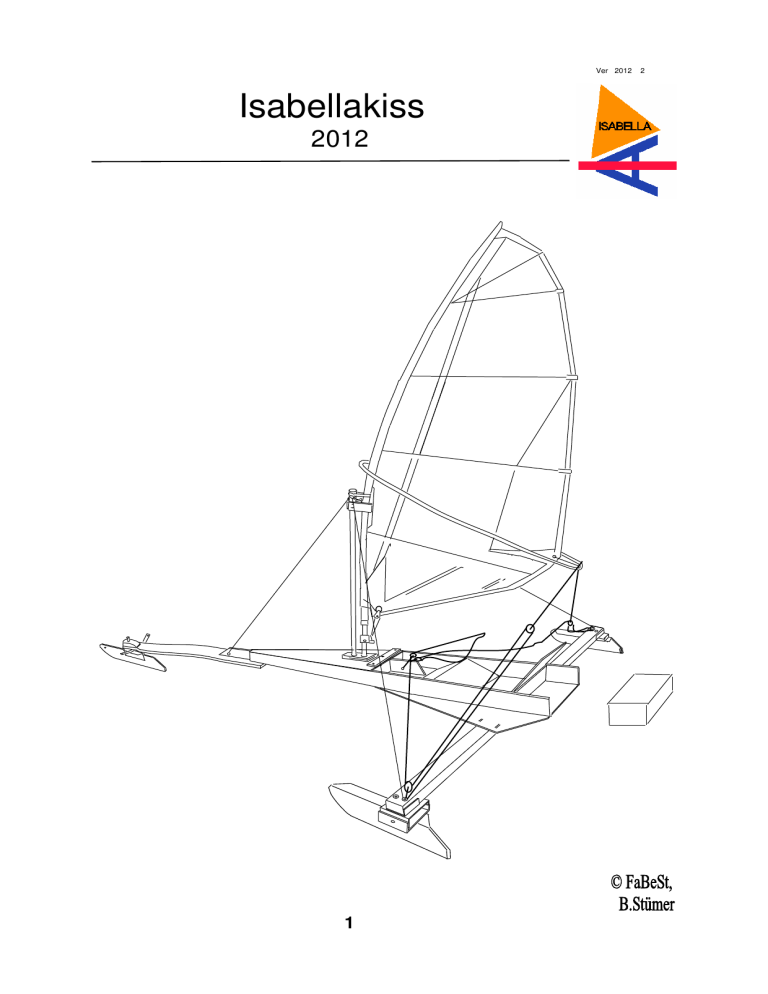
Isabellakiss
Mera KISS för Isabellan.
Inget snickrande av lådan baki.
En plastback med lock kläms mellan sidobrädorna som går ut i aktern.
Bottenplywood går förbi sidobrädorna i aktern.
Två remmar fäster skrov mot plankan.
Vinkeln under knäna håller ihop sidobrädorna.
Frigolit i nosen och i vinkeln under knäna.
Lätt som en plätt.
More KISS for Isabella.
None of the carpentry on a box aft.
A plastic box with lid is clamped between the side boards that go into the stern.
Bottomplywood passes the side boards in the stern.
Two straps attach to the hull plank.
The angle under the knees hold together the side boards.
Styrofoam in the nose and the angle below the knees.
Piece of cake.
2
Mått
Measurements
Botten plywood
Bottom
skarv av botten
splice bottom
Nosbräda
Springboard
ung 3,20 M total skrovlängd
about total hull length
skarv av botten
splice bottom
Mastfot 135 cm från plankan
Mastfoot 135 in front of plank
Skott som passar dina mått
Bulkheads fit your size
Vinkel under knäna
Angle under knee
Ryggstöd
Seatback
För rem
Holes for belt
1 meter
3
Planka
Plank
Nya beslag
New steel-work
Förmedhållare
Front - chock
Fäste för styrlinor
Alternative
Nosbräda
4
Sidomedhållare
Side - chock
C
Del A och B är exakt lika.
Del C håller plankan.
Alla bulthål i delarna och
meden är exakt lika.
Delarna bultas tillsammans med M8 bult.
B
Part A and B are exakt
the same.
Part C is holding the runnerplank.
All bolt-holes are exact
the same.
The parts are bolted together with M8– bolts.
A
Delarna A och B går omlott.
Undre delen A skall sitta
på utsidan av B.
The parts A and B are
overlapped.
Part A from the outside.
5
Nya beslag 2010
Mede 600 mm 130 mm hög, vinklad 40 mm.
Vinkel skall var 5 grader överknäckt, toe in, så att meden möter isen vinkelrät när
plankan sviktar nedåt.
Mede kan också göras av vinkeljärn, 50x100x 6mm finns som standard men då
måste en kil under planknocken så att meden vinklas toe in.
Bulthålen blir i detta fall där den genomgående bulten går genom över– och underdelen av medhållarna. Här roterar meden längs med. Bulthål från aktern
245mm sidomede, 278mm styrmede
Sidohållaren består av tre bockade 4mm plåtar, en överdel, C sid 3, som greppar
över plankan och håller bultarna som håller den nästa bricka B på plats omlott A i
den uppbockade delen. Sid. 3.
Det enda mått som måste hållas är delen C där 95 mm skall greppa över plankan
45x95x2500 mm. Hur höga de uppvikta kanterna är beror lite på pressverktygen i
kantpressen. 40mm vore bra.
Viktigt är att meden kan rotera i längdriktning åtminstone 10-20grader.
Medens egg måste ha en kurva med 2mm på 400mm åkyta nedanför rotationspunkten och eggen kan antingen slipas som stämjärn med kant utåt eller som 90 graders egg, 45 gr från var sida.
Förmedhållare
Samma över– och underdelar som i sidomedhållarna används.
Men ytterligare ett hål för styrbulten måste finnas.
Under överdelen ligger en vinkel i vilken styrlinorna är fästa.
Styrbulten håller underifrån också styrvingarna där styrstagen är fästa, två linor.
6
New steelwork 2012
The runners are made of standard steel 600x130x5 to 6 mm where a angle 40 mm
is pressed.
The runner can also be made of angle iron 50x100x 6mm and this is available as
standard-steel.
Bolt holes is in this case where the through-bolt through the upper B and lower A
parts of the backed makers. It rotates along the runner. Bolt holes from the stern
245mm side runner, 278mm steering runner. Side 3.
Side chock-holder consists of three bended 4 mm plates, one part that grips the
plank and keep the bolts that hold the next tray in place and two others overlapping
each other in the up bended part.
The only dimension needed is the dimension of the runner-plank which has to fit in
part C. We use 95x45 mm wood as the plank. How high the upturned edges are
due to press tools in the press. 40mm would be good.
Important is the runner to rotate in the longitudinal direction of at least 10-20grader.
The runners must have a curve of 2mm to 400mm glide surface beneath the pivot
point and an edge can either be ground to chisel edge outwards or 90 degree edge,
45 degrees from each side.
Runners must tilt 5 degrees toe in for it to hit the ice at a right angle when the plank
bends down when sailing. A wedge is glued and screwed in the wooden ridge when
right-angeled steel is used.
Front runner chock-holder
The same upper and lower parts of the side chock-holder are used.
But another hole for the steering bolt must be made.
The steering bolt holds from underneath the wings on which track rods are attached,
two ropes.
Note
We have not been able to real test the new steel-work on the ice.
We have to test more.
7


